Cable the Roving Edge Device
Use the following diagrams to locate connectors on the rear of the Roving Edge Device as you connect cables in this procedure.
To meet MIL-STD-461 Rev G RE102 requirements, all Ethernet network cables attached to the Roving Edge Device must be CAT8 rated. Otherwise, the minimum requirement for Ethernet cables is CAT6.
The Ethernet connections described in this section are the minimum Ethernet connections you need to make to set up the device. You can use the other NIC ports and configure Ethernet bonding. See Identify Front and Rear Panel Items and Managing Ethernet Bonding.
Most devices require you to download a large 25 GB software file to self-provision the device. To ensure a smooth installation, we recommend connecting the device to a high-speed network.
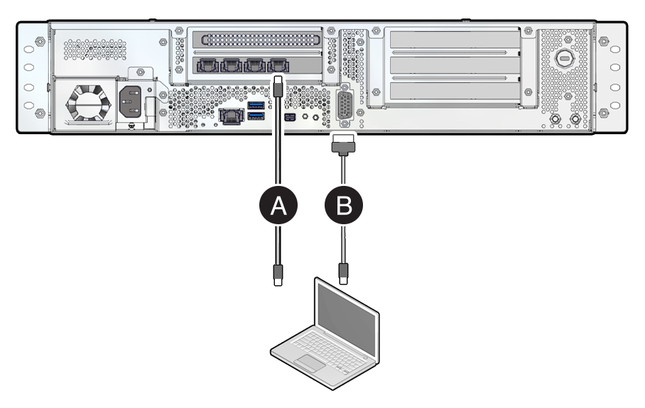
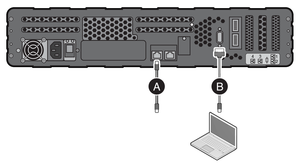
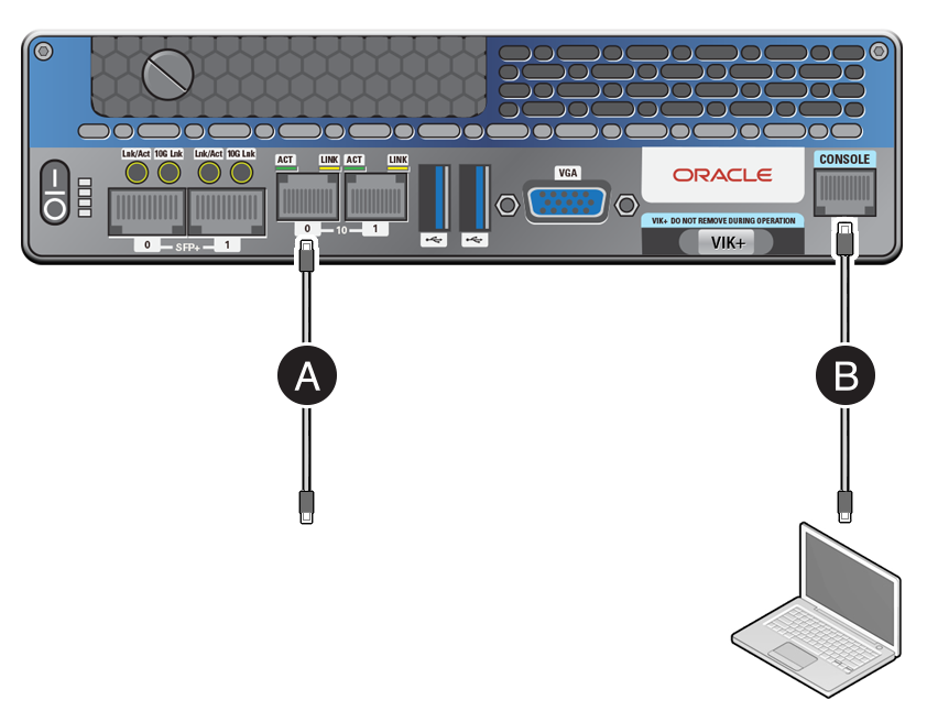
Connect cables to the default Ethernet port and to the serial console port as shown in the following diagrams.
Note
For initial installation and self-provisioning, ensure that the device isn't behind an HTTP proxy server and that the device has internet connectivity. After self-provisioning, you can move the device behind an HTTP proxy server.
-
Use a 10GBaseT RJ-45 Ethernet cable to connect the device Ethernet port to your Ethernet switch.
-
Connect the provided USB serial cable from the device serial console port to a USB connector on your controlling host, such as a laptop.
Roving Edge Device 2: Compute, GPU, and Storage Shapes
Roving Edge Device 1
Roving Edge Ultra
-
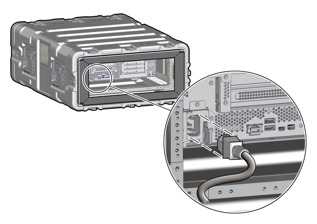
Connect the provided power cord to the device power receptacle and to your power source, but don't power on the device yet.
For Roving Edge Ultra, connect the power cord to the AC connector on the rear of the device.
The following illustration shows where to connect the power cable on a Roving Edge Device 2 that's in a ruggedized case.
What's next?