Routing Network Traffic to a Firewall

Scenarios showing how to route network traffic to a firewall.

This topic shows several scenarios for routing traffic to a network firewall. See the following resources for more information about network routing:
Important

  • For better performance, Oracle recommends that you don't add stateful rules to the security list attached to the firewall subnet or include the firewall in a network security group (NSG) containing stateful rules.
  • Security list or network security group (NSG) rules associated with the firewall subnet and VNICs are evaluated before the firewall. Be sure that any security list or NSG rules allow the traffic to enter the firewall so that it can be evaluated appropriately.
  • If the policy you use with the firewall doesn't have any rules specified, the firewall denies all traffic.
To route on-premises traffic through a firewall

Here's an example of how to set up routing from an on-premises network to your Oracle Cloud Infrastructure VCN using a Dynamic Routing Gateway (DRG) Each step contains a link to specific instructions:

  1. Create a DMZ subnet in the VCN.
  2. In the DMZ subnet, create a firewall and associate it with a policy.
  3. Create a dynamic routing gateway (DRG).
  4. Create a DRG route table.
  5. Attach the VCN to the DRG. When setting up the attachment, associate the DRG route table to the attachment as specified in Step 6 of the Attach the VCN to the DRG instructions.
  6. Add an intra-VCN route rule to the DRG route table that specifies a destination CIDR within the VCN CIDR (for example, 10.0.1.0/24), and target the firewall IP address (for example, 10.0.2.2).
  7. Update the private subnet to route all traffic to on-premise or other regions through the firewall.
  8. Update the DMZ subnet to route traffic to on-premise or another VCN in the same or different regions through the DRG.

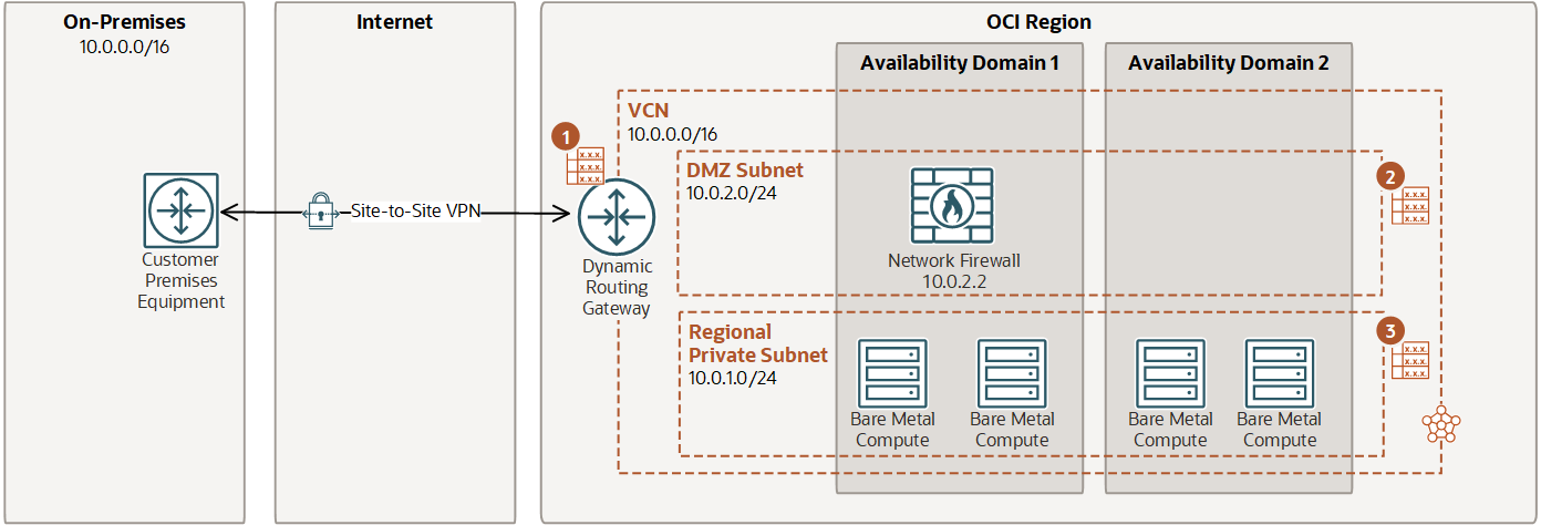
    This image shows on-premises routing to a VCN using a DRG.
    Callout 1: Dynamic routing gateway (DRG) route table
    Destination CIDR Route target
    0.0.0.0/0 Network Firewall (10.0.2.2)
    Callout 2: DMZ subnet route table
    Destination CIDR Route target
    0.0.0.0/0 DRG
    Callout 3: DMZ subnet route table
    Destination CIDR Route target
    0.0.0.0/0 Network Firewall (10.0.2.2)
To route internet traffic through a firewall

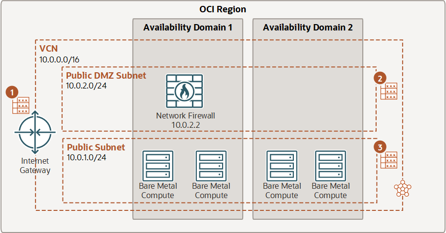
In this example, routing is configured from the internet to the firewall. Traffic is routed from the IGW, through the firewall, and then from the firewall subnet to a public subnet.

  1. Create a DMZ subnet in the VCN.
  2. In the DMZ subnet, create a firewall and associate it with a policy.
  3. Create an internet gateway in the VCN.
  4. Add an intra-VCN route rule to the IGW route table that specifies a destination CIDR within the VCN CIDR (for example, 10.0.1.0/24), and target the firewall IP address (for example, 10.0.2.2)
  5. Update the public subnet route table to route all traffic to the internet through the firewall.
  6. Update the DMZ subnet to route traffic to the internet through the IGW.

    This image shows routing from an internet gatway to a firewall.
    Callout 1: Internet gateway (IGW) route table
    Destination CIDR Route target
    VCN (10.0.0.0/16) Network Firewall (10.0.2.2)
    Callout 2: DMZ subnet route table
    Destination CIDR Route target
    0.0.0.0/0 IGW
    Callout 3: Public subnet route table
    Destination CIDR Route target
    0.0.0.0/0 Network Firewall (10.0.2.2)
To route intra-VCN traffic through a firewall

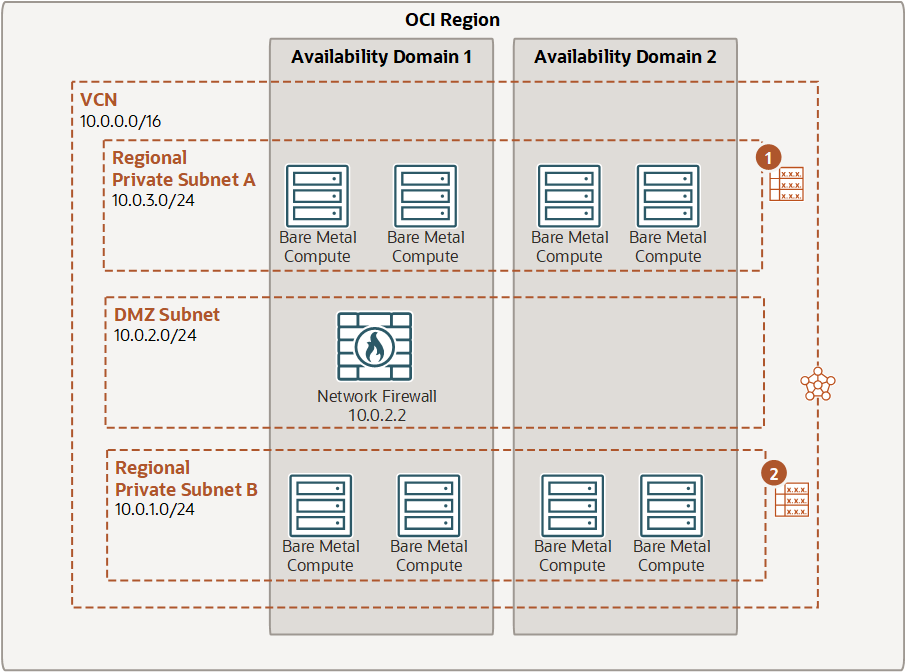
In this example, traffic is routed from Subnet A, to the firewall. From the firewall, traffic is routed to Subnet B using the implicit 10.0.0.0 to "local" (not shown).
  1. Create Subnet A in the VCN.
  2. Create Subnet B in the VCN.
  3. Create a DMZ subnet in the VCN.
  4. In the DMZ subnet, create a firewall and associate it with a policy.
  5. Add an intra-VCN route rule to the Subnet A route table that specifies a destination CIDR within the VCN CIDR (for example, 10.0.1.0/24), and target the firewall IP address (for example, 10.0.2.2)
  6. Add a route rule to Subnet B that specifies the destination with the VCN (10.0.3.0/24) throught the firewall.

    This image shows intra-VCN routing though the network firewall.
    Callout 1: Regional private subnet A route table
    Destination CIDR Route target
    Subnet B (10.0.1.0/24) Network Firewall (10.0.2.2)
    Callout 2: Regional private subnet B route table
    Destination CIDR Route target
    Subnet A (10.0.3.0/24) Network Firewall (10.0.2.2)