FortiGate
This topic provides configuration for a FortiGate running software version 6.0.4.
FortiGate experience is recommended. For more details on how to use FortiGate products, visit their official site. For FortiGate documentation for high availability (HA) or manual deployment, see the Fortinet Document Library.
Oracle provides configuration instructions for a tested set of vendors and devices. Use the correct configuration for the vendor and software version.
If the device or software version that Oracle used to verify the configuration doesn't exactly match the device or software, you might still create the necessary configuration on the device. Consult the vendor's documentation and make any necessary changes.
If the device is from a vendor not in the list of verified vendors and devices, or if you're already familiar with configuring the device for IPSec, see the list of supported IPSec parameters and consult the vendor's documentation for help.
Oracle Cloud Infrastructure offersSite-to-Site VPN, a secure IPSec connection between an on-premises network and a virtual cloud network (VCN).
The following diagram shows a basic IPSec connection to Oracle Cloud Infrastructure with redundant tunnels. IP addresses used in this diagram are for example purposes only.
Best Practices
This section covers general best practices and considerations for using Site-to-Site VPN.
Configure All Tunnels for Every IPSec Connection
Oracle deploys two IPSec headends for connections to provide high availability for mission-critical workloads. On the Oracle side, these two headends are on different routers for redundancy purposes. We recommend configuring all available tunnels for maximum redundancy. This is a key part of the "Design for Failure" philosophy.
Have Redundant CPEs in On-Premises Network Locations
We recommend that each site that connects with IPSec to Oracle Cloud Infrastructure has redundant edge devices (also known as customer-premises equipment (CPE)). You add each CPE to the Oracle Console and create a separate IPSec connection between a dynamic routing gateway (DRG) and each CPE. For each IPSec connection, Oracle provisions two tunnels on geographically redundant IPSec headends. For more information, see the Connectivity redundancy guide (PDF).
Routing Protocol Considerations
When you create a Site-to-Site VPN IPSec connection, it has two redundant IPSec tunnels. Oracle encourages you to configure the CPE to use both tunnels (if the CPE supports it). In the past, Oracle created IPSec connections that had up to four IPSec tunnels.
The following three routing types are available, and you select the routing type separately for each tunnel in the Site-to-Site VPN:
- BGP dynamic routing: The available routes are learned dynamically through BGP. The DRG dynamically learns the routes from the on-premises network. On the Oracle side, the DRG advertises the VCN's subnets.
- Static routing: When you set up the IPSec connection to the DRG, you specify the particular routes to the on-premises network that you want the VCN to know about. You also must configure the CPE device with static routes to the VCN's subnets. These routes aren't learned dynamically.
- Policy-based routing: When you set up the IPSec connection to the DRG, you specify the particular routes to the on-premises network that you want the VCN to know about. You also must configure the CPE device with static routes to the VCN's subnets. These routes aren't learned dynamically.
For more information about routing with Site-to-Site VPN, including Oracle recommendations on how to manipulate the BGP best path selection algorithm, see Routing for Site-to-Site VPN.
Other Important CPE Configurations
Ensure that access lists on the CPE are configured correctly to not block necessary traffic from or to Oracle Cloud Infrastructure.
If you have several tunnels up simultaneously, you might experience asymmetric routing. To account for asymmetric routing, ensure that the CPE is configured to handle traffic coming from the VCN on any of the tunnels. For example, you need to disable ICMP inspection, configure TCP state bypass . For more details about the appropriate configuration, contact the CPE vendor's support. To configure routing to be symmetric, see Routing for Site-to-Site VPN.
Caveats and Limitations
This section covers general important characteristics and limitations of Site-to-Site VPN to be aware of. See Limits by Service for a list of applicable limits and instructions for requesting a limit increase.
Asymmetric Routing
Oracle uses asymmetric routing across the tunnels that make up the IPSec connection. Configure firewalls with that in mind. Otherwise, ping tests or application traffic across the connection don't work reliably.
When you use several tunnels to Oracle Cloud Infrastructure, We recommend that you configure routing to deterministically route traffic through the preferred tunnel. To use one IPSec tunnel as primary and another as backup, configure more-specific routes for the primary tunnel (BGP) and less-specific routes (summary or default route) for the backup tunnel (BGP/static). Otherwise, if you advertise the same route (for example, a default route) through all tunnels, return traffic from a VCN to an on-premises network routes to any of the available tunnels. This is because Oracle uses asymmetric routing.
For specific Oracle routing recommendations about how to force symmetric routing, see Routing for Site-to-Site VPN.
Route-Based or Policy-Based Site-to-Site VPN
The IPSec protocol uses Security Associations (SAs) to decide how to encrypt packets. Within each SA, you define encryption domains to map a packet's source and destination IP address and protocol type to an entry in the SA database to define how to encrypt or decrypt a packet.
Other vendors or industry documentation might use the term proxy ID, security parameter index (SPI), or traffic selector when referring to SAs or encryption domains. Access Lists are also a common Cisco term for Encryption Domains.
There are two general methods for implementing IPSec tunnels:
- Route-based tunnels: Also called next-hop-based tunnels. A route table lookup is performed on a packet's destination IP address. If that route's egress interface is an IPSec tunnel, the packet is encrypted and sent to the other end of the tunnel.
- Policy-based tunnels: The packet's source and destination IP address and protocol are matched against a list of policy statements. If a match is found, the packet is encrypted based on the rules in that policy statement.
The Oracle Site-to-Site VPN headends use route-based tunnels but can work with policy-based tunnels with some caveats listed in the following sections.
If the CPE supports route-based tunnels, use that method to configure the tunnel. This is the simplest configuration with the most interoperability with the Oracle VPN headend.
Route-based IPSec uses an encryption domain with the following values:
- Source IP address: Any (0.0.0.0/0)
- Destination IP address: Any (0.0.0.0/0)
- Protocol: IPv4
If you need to be more specific, you can use a single summary route for encryption domain values instead of a default route.
When you use policy-based tunnels, every policy entry (a CIDR block on one side of the IPSec connection) that you define generates an IPSec security association (SA) with every eligible entry on the other end of the tunnel. This pair is referred to as an encryption domain.
In this diagram, the Oracle DRG end of the IPSec tunnel has policy entries for three IPv4 CIDR blocks and one IPv6 CIDR block. The on-premises CPE end of the tunnel has policy entries two IPv4 CIDR blocks and two IPv6 CIDR blocks. Each entry generates an encryption domain with all possible entries on the other end of the tunnel. Both sides of an SA pair must use the same version of IP. The result is a total of eight encryption domains.
If the CPE only supports policy-based tunnels, be aware of the following restrictions.
- Site-to-Site VPN supports multiple encryption domains, but has an upper limit of 50 encryption domains.
- If you had a situation similar to the prior example and only configured three of the six possible IPv4 encryption domains on the CPE side, the link would be listed in a "Partial UP" state because all possible encryption domains are always created on the DRG side.
- Depending on when a tunnel was created you might not be able to edit an existing tunnel to use policy-based routing and might need to replace the tunnel with a new IPSec tunnel.
- The CIDR blocks used on the Oracle DRG end of the tunnel can't overlap the CIDR blocks used on the on-premises CPE end of the tunnel.
- An encryption domain must always be between two CIDR blocks of the same IP version.
If the CPE Is Behind a NAT Device
In general, the CPE IKE identifier configured on the on-premises end of the connection must match the CPE IKE identifier that Oracle is using. By default, Oracle uses the CPE's public IP address, which you provide when you create the CPE object in the Oracle Console. However, if a CPE is behind a NAT device, the CPE IKE identifier configured on the on-premises end might be the CPE's private IP address, as shown in the following diagram.
Some CPE platforms don't let you change the local IKE identifier. If you can't, you must change the remote IKE ID in the Oracle Console to match the CPE's local IKE ID. You can provide the value either when you set up the IPSec connection, or later, by editing the IPSec connection. Oracle expects the value to be either an IP address or a fully qualified domain name (FQDN) such as cpe.example.com. For instructions, see Changing the CPE IKE Identifier That Oracle Uses.
Supported IPSec Parameters
For a vendor-neutral list of supported IPSec parameters for all regions, see Supported IPSec Parameters.
The Oracle BGP ASN for the commercial cloud realm is 31898. If you're configuring Site-to-Site VPN for the US Government Cloud, see Required Site-to-Site VPN Parameters for Government Cloud and also Oracle's BGP ASN. For the United Kingdom Government Cloud, see Regions.
CPE Configuration
The configuration instructions in this section are provided by Oracle Cloud Infrastructure for this CPE. If you need support or further help, contact the CPE vendor's support directly.
The following figure shows the basic layout of the IPSec connection.
By default, FortiGate provisions the IPSec tunnel in route-based mode. This topic focuses on FortiGate with a route-based VPN configuration.
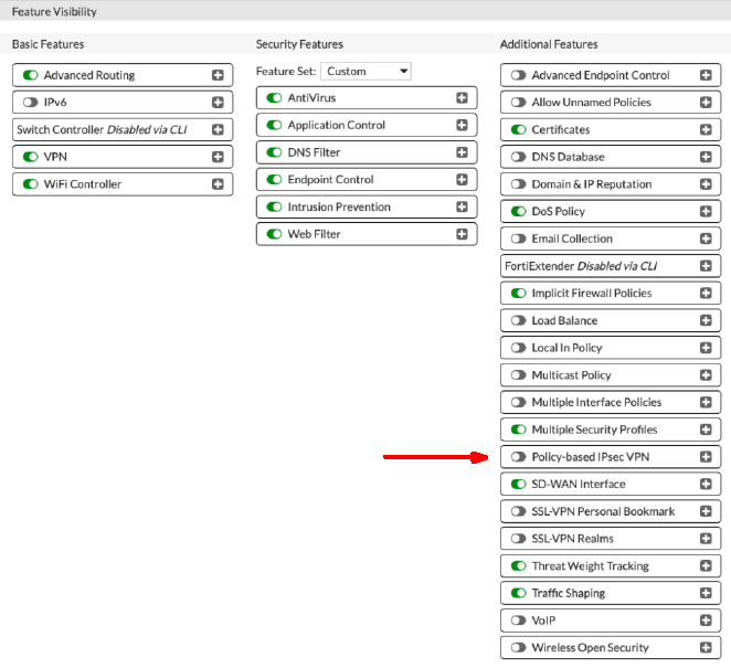
You can have FortiGate provision the IPSec tunnel in policy-based mode. To enable the feature, go to System, and then to Feature Visiblity. Under Additional Features, enable the Policy-based IPSec VPN feature.
About Using IKEv2
Oracle supports Internet Key Exchange version 1 (IKEv1) and version 2 (IKEv2). If you configure the IPSec connection in the Console to use IKEv2, you must configure the CPE to use only IKEv2 and related IKEv2 encryption parameters that the CPE supports. For a list of parameters that Oracle supports for IKEv1 or IKEv2, see Supported IPSec Parameters.
To use IKEv2, use a variation on one of the tasks presented in the next section. In task 2, when configuring authentication, select IKE version 2.
Configuration Process
Before starting, ensure you have a valid license or trial license to configure FortiGate.
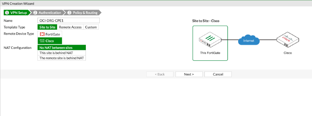
- Go to VPN, and then to IPSec Wizard to create a new VPN tunnel.
- On the VPN Creation Wizard page, specify the following items:
- Name: Description used to identify the IPSec tunnel. Avoid entering confidential information.
- Template Type: Site to Site
- Remote Device Type: Cisco
- NAT Configuration: No NAT between sites
- Select Next.
- On the Authentication page, specify the following items:
- Remote Device: IP Address
- IP Address: IP address for the Oracle VPN headend. Oracle generated this value when creating the IPSec tunnel.
- Outgoing Interface: The WAN interface configured for external traffic.
- Authentication Method: Pre-shared Key. Oracle supports only shared secret keys.
- Pre-shared Key: The shared secret. Oracle generated this value when creating the IPSec tunnel.
- Select Next.
- On the Policy & Routing page, specify the following items:
- Local Interface: The LAN interface configured for internal traffic.
- Local Subnets: The subnet used for internal traffic.
- Remote Subnets: The Oracle VCN subnets that can access the IPSec tunnel.
- Internet Access: None
-
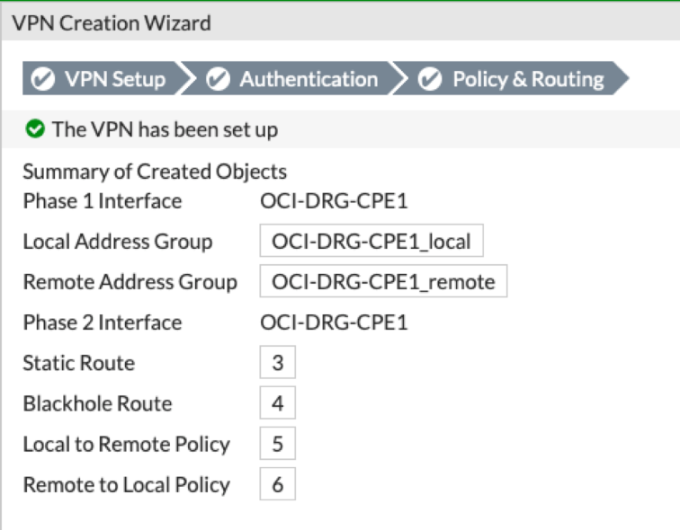
Select Create.
A summary message is shown with details about the configuration. Notice that the wizard automatically creates security policies with the subnets that you specified and adds the required static routes.
You must convert each newly created IPSec tunnel into a custom tunnel to add the recommended parameters for Phase 1 and Phase 2.
Perform the following steps for each tunnel.
- Go to VPN, and then select IPsec Tunnels.
- Select the tunnel and select Edit to view the Edit VPN Tunnel page.
-
Select Convert to Custom Tunnel.
-
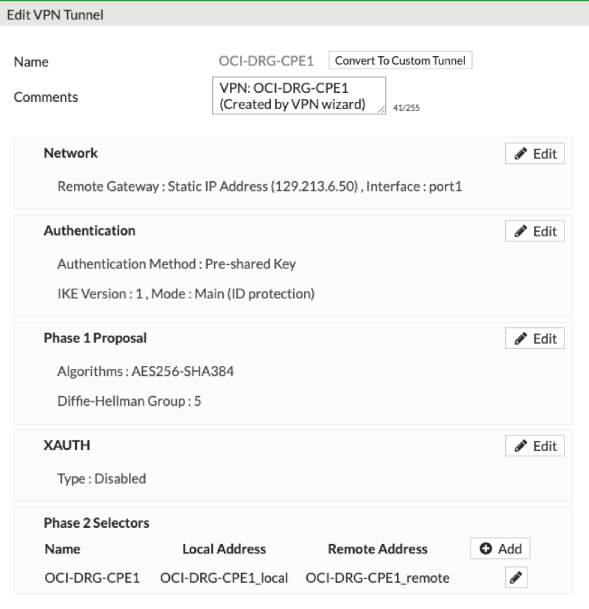
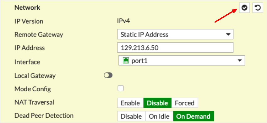
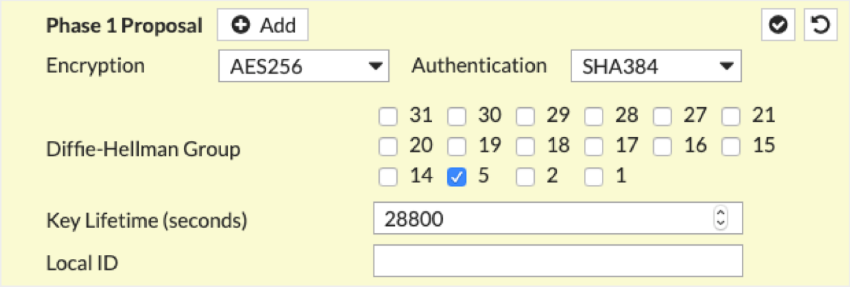
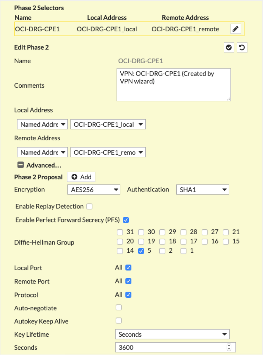
Edit the relevant sections to match the required settings shown in the following screenshots. Remember to select the check mark icon in the upper-right corner of each section after making changes.
The IP address shown in the first screenshot is an example address.
Notice that to use IKEv2, on the Authentication screen, instead select IKE Version 2.
- After configuring all sections, select OK to save and close the dialogs.
At this point, the IPSec tunnel isn't established by default because FortiGate uses the IP address assigned on the WAN interface. In this case, this IP address is a private IP address because Oracle does 1:1 NAT. This private IP address gets used as the local IKE ID and doesn't match the one expected on the Oracle DRG. To resolve this, you can manually change the local IKE ID on the FortiGate by using the CPE's CLI, or you can change the value that Oracle uses in the Oracle Console (see the instructions that follow). Either way, this fixes the incompatibility and brings up the IPSec tunnel.
- Open the navigation menu and select Networking. Under Customer connectivity, select Site-to-Site VPN.
A list of the IPSec connections in the compartment that you're viewing is displayed. If you don't see the policy you're looking for, verify that you're viewing the correct compartment. To view policies attached to a different compartment, under List scope, select that compartment from the list.
-
For the IPSec connection you're interested in, select the , and then select Edit.
The current CPE IKE identifier that Oracle is using is displayed at the bottom of the dialog.
- Enter new values for CPE IKE Identifier Type and CPE IKE Identifier, and then select Save Changes.
Redundancy with BGP Over IPSec
For redundancy, we recommend using BGP over IPSec. By default, if you have two connections of the same type (for example, two IPSec VPNs that both use BGP), and you advertise the same routes across both connections, Oracle prefers the oldest established route when responding to requests or starting connections. To force routing to be symmetric, we recommend using BGP and AS path prepending with routes to influence which path Oracle uses when responding to and starting connections. For more information, see Routing Details for Connections to the On-premises Network.
The Oracle DRG uses /30 or /31 as subnets for configuring IP addresses on the interface tunnels. Remember that the IP address must be part of Site-to-Site VPN's encryption domain and must be allowed in the firewall policy to reach the peer VPN through the interface tunnel. You might need to implement a static route through the tunnel interface for the peer IP address.
Oracle's BGP ASN for the commercial cloud is 31898, except the Serbia Central (Jovanovac) region which is 14544. If you're configuring Site-to-Site VPN for the Government Cloud, see Required Site-to-Site VPN Parameters for Government Cloud and also Oracle's BGP ASN.
For the on-premises side, you can use a private ASN. Private ASNs are in the range 64512–65534.
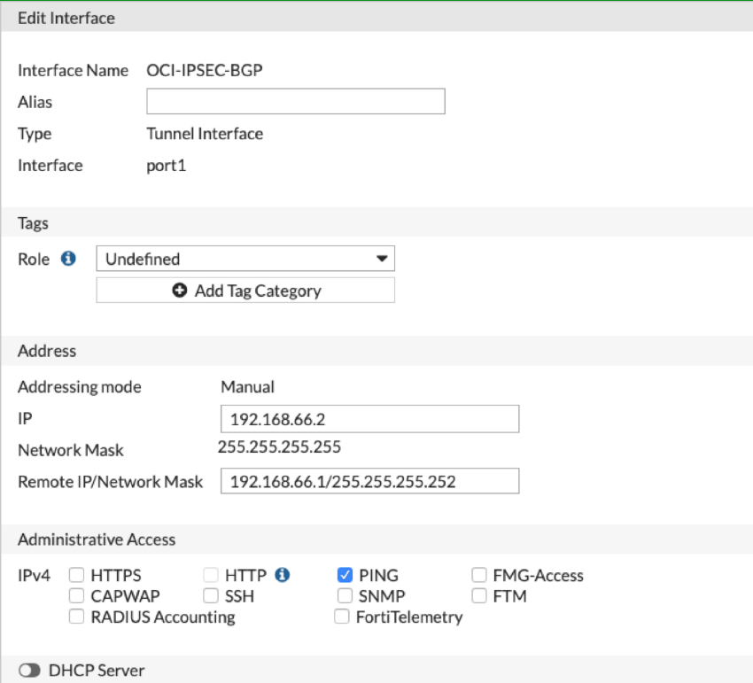
In the first task, you add the BGP IP address to the newly created FortiGate tunnel interface.
Perform the following steps for each tunnel.
- Go to Network, and then Interface.
- Select the interface you're interested in and select Edit.
- Configure the following items:
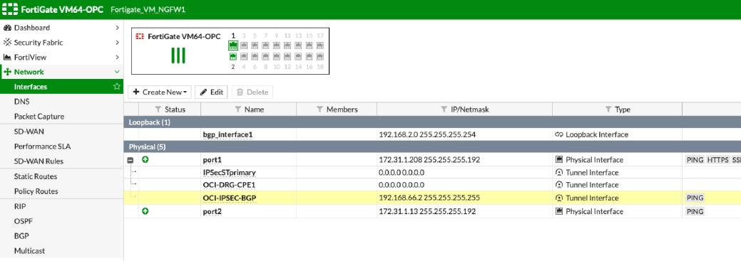
- IP: Enter the BGP IP address that you assigned to the FortiGate end of the tunnel interface. The following screenshot shows an example value of 192.168.66.2.
- Remote IP/Network Mask: Add the BGP IP address that you assigned to the Oracle end of the tunnel interface. Include either a /30 or /31 mask, depending on how you specified the addresses in the Oracle Console. In the following screenshot, 192.168.66.0/30 was used, where 192.168.66.2 is assigned to the FortiGate end, and 192.168.66.1 is assigned to the Oracle end.
-
Ping access (recommended): In the Administrative Access section, enable ping access.
- Select OK.
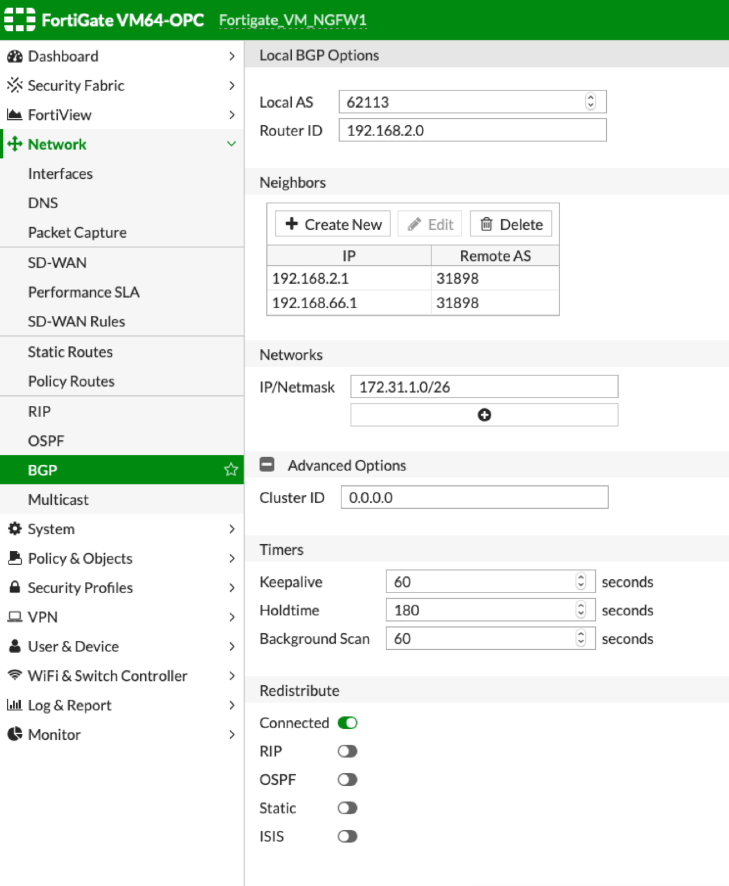
Perform the following steps for each tunnel.
- Go to Network, and then BGP.
- Enter the following items:
- Local AS: The on-premises BGP ASN. You can use a private ASN. Private ASNs are in the range 64512–65534.
- Router ID: A value to provide a unique identity for this BGP router among its peers.
- Neighbors: Select Create New and enter the BGP IP address for the Oracle end of the tunnel, and the Oracle BGP ASN. Oracle's BGP ASN for the commercial cloud is 31898, except the Serbia Central (Jovanovac) region which is 14544. If you're configuring Site-to-Site VPN for connecting to the Government Cloud, see Oracle's BGP ASN.
-
Networks: Optionally use this field to advertise a specific subnet over BGP. You can also advertise subnets by using the Redistribute section in the Advanced Options section.
- Select OK.
Verification
The following CLI command is useful for gathering statistical data such as the number of packets encrypted and decrypted, the number of bytes sent and received, the encryption domain (SPI) identifier, and so on. This kind of information can be critical for finding an issue with the VPN.
diagnose vpn tunnel listThe following command indicates a lack of firewall policy, a lack of forwarding route, and policy ordering issues. If there are no communication issues, this command returns blank output.
diagnose debug flowThe following command verifies BGP neighbor status information. Remember that an "Active" state doesn't mean that the BGP session is up. "Active" refers to a BGP state message. For more information, see BGP Background and Concepts in the FortiGate documentation.
get router info bgp summaryThe following command provides more detailed information about a BGP neighbor.
get router info bgp neighborsA Monitoring service is also available from Oracle Cloud Infrastructure to actively and passively monitor cloud resources. For information about monitoring a Site-to-Site VPN, see Site-to-Site VPN Metrics.
If you have issues, see Site-to-Site VPN Troubleshooting.


